Connecting & Powering up
Overview
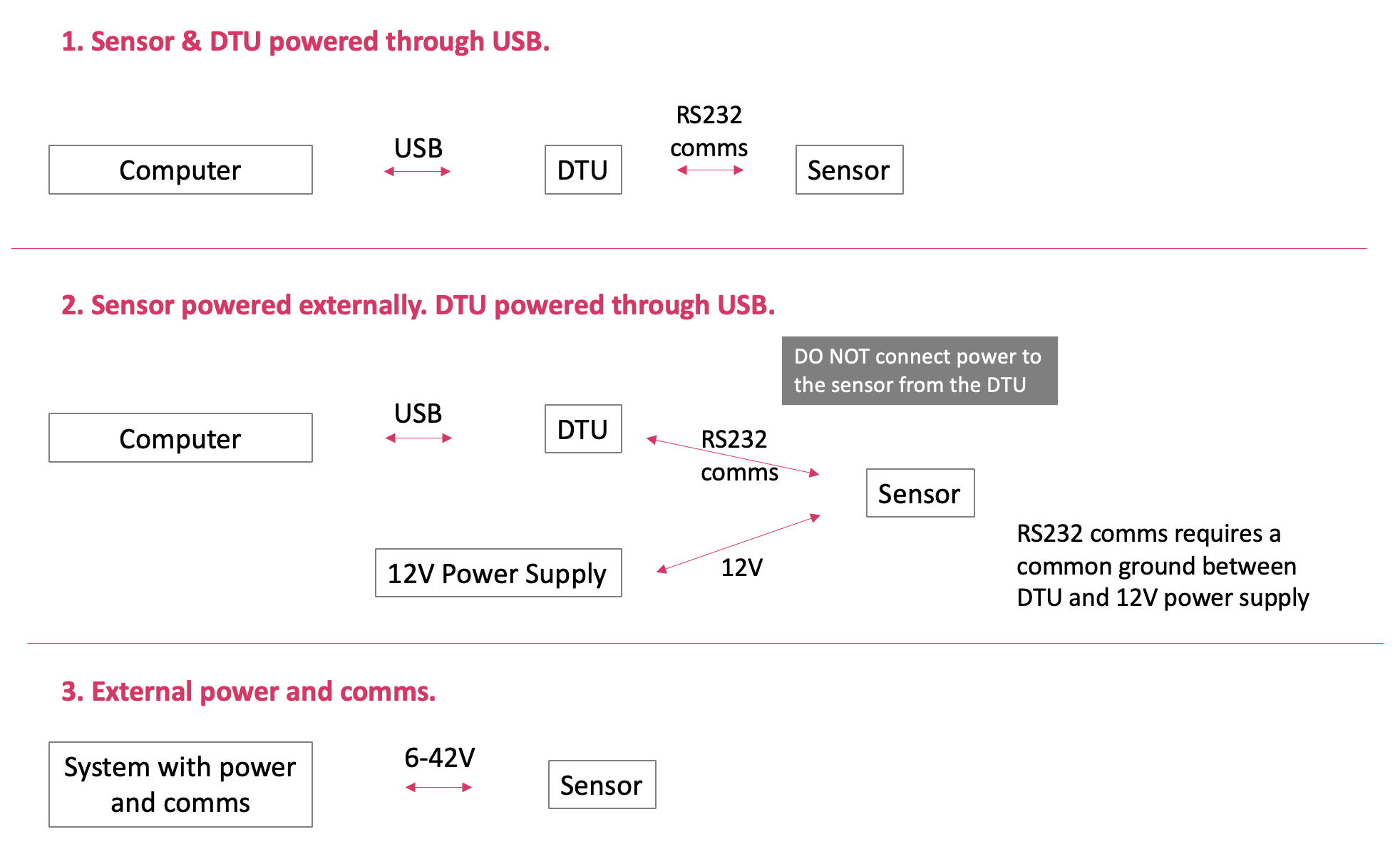
There are three methods to power and communicate with your sensor:
Connecting
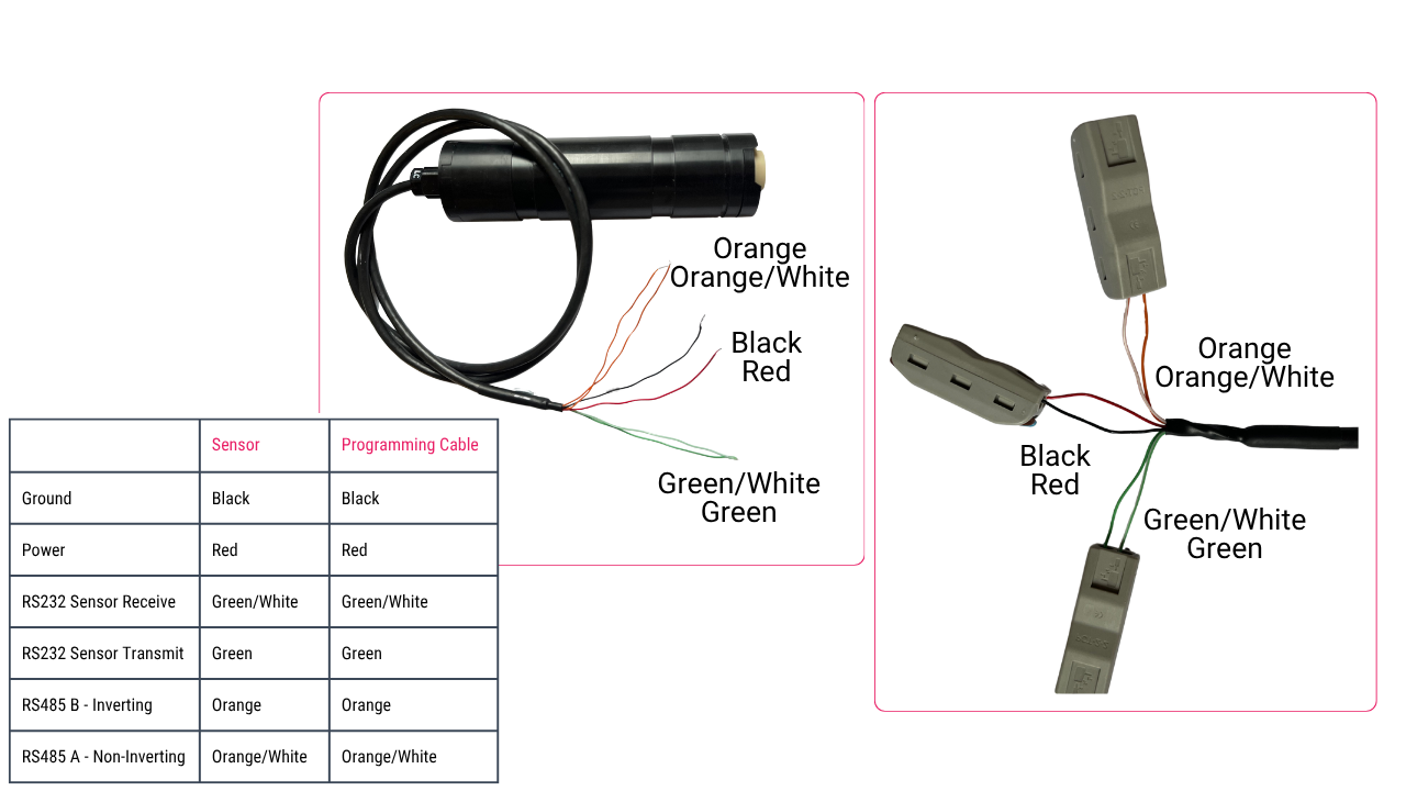
Pigtail cabled sensors
Sensors terminated with a 6-core pigtailed cable should be connected as shown in the diagram below.
Sensors of an earlier revision, identifiable by a blue wire, should be connected using this alternative diagram.
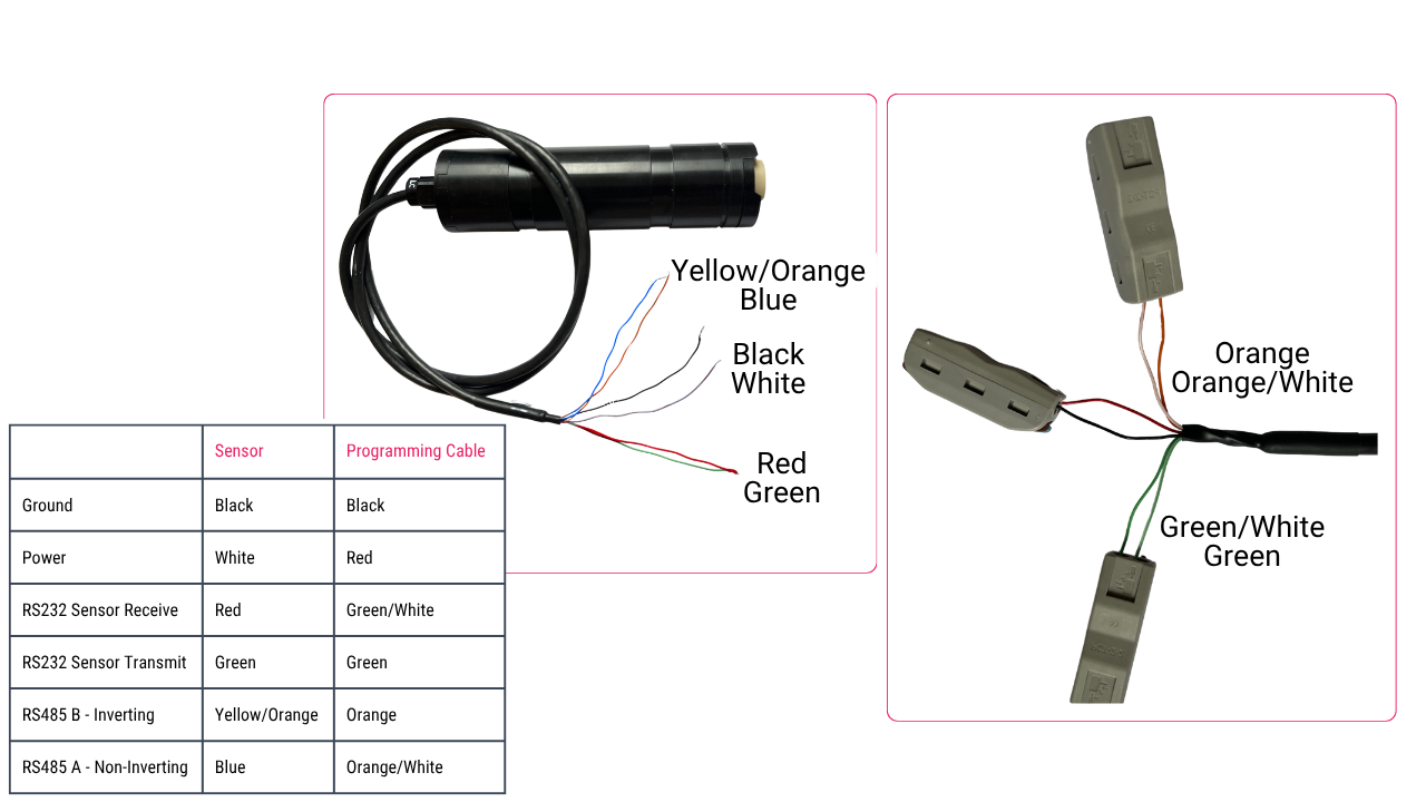
Because of the potential for different vendors to use different signal definitions, if you connect our sensors' A/B wiring to your communication device and communication does not work, try reversing the signals
SubConn cabled sensors
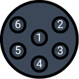
For sensors terminated using a MCBH6M connector, follow the pin-out below:
| Pin | Function |
|---|---|
| 1 | Ground |
| 2 | Power |
| 3 | RS232 Sensor Receive |
| 4 | RS232 Sensor Transmit |
| 5 | RS485 B - Inverting (for sensors with a serial number > 3000028) |
| 6 | RS485 A - Non-Inverting (for sensors with a serial number > 3000028) |
Because of the potential for different vendors to use different signal definitions, if you connect our sensors' A/B wiring to your communication device and communication does not work, try reversing the signals
Powering
The sensor can be simply powered by any power source (6-42V) or via the DTU from a USB port of a computer.
Via battery
- Connect the sensor to power
- Wait for the sensor to beep twice
Via the DTU
- Connect the sensor to the DTU and the USB to the computer
- Press the power on switch on the DTU and the light will come on to show the DTU has power
- Wait for the sensor to beep twice